Распайка разъема блока питания АТХ
(Power Supply Connector)
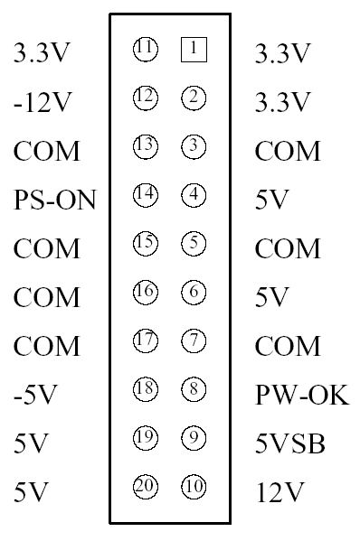
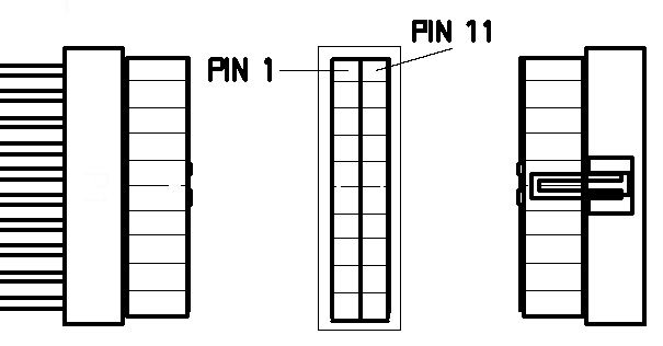
Figure shows the connector pinout for the main ATX power connector. This
board-mounted header may be
implemented with a Molex 39-29-9202 or equivalent. This mates with the power
supply connector, Molex 39-
01-2200 or equivalent. All signals and power rails on the main power connector
are required to be implemented.
During power-up and power-down transitions, it is recommended that the 3.3VDC
rails always be held at a lower
potential than the +5VDC rails. This allows for improved reliability of
motherboard designs at a reduced cost.
Proper implementation of PS-ON, 5VSB, and PW-OK is required for an ATX
2.01-compliant power supply.
| 18 AWG Wire |
Signal |
Pin |
Pin |
Signal |
18 AWG Wire |
Orange(22AWG)
Brown(22AWG) |
+3.3 VDC
3.3V sense |
11
11 |
1 |
+3.3 VDC |
Orange |
| Blue |
-12 VDC |
12 |
2 |
+3.3 VDC |
Orange |
| Black |
COM |
13 |
3 |
COM |
Black |
| Green |
PS-ON |
14 |
4 |
+5 VDC |
Red |
| Black |
COM |
15 |
5 |
COM |
Black |
| Black |
COM |
16 |
6 |
+5 VDC |
Red |
| Black |
COM |
17 |
7 |
COM |
Black |
| White |
-5 VDC |
18 |
8 |
POK |
Gray |
| Red |
+5 VDC |
19 |
9 |
+5VSB |
Purple |
| Red |
+5 VDC |
20 |
10 |
+12 VDC |
Yellow |
PS-ON is an active low signal that turns on all of the main power rails
including 3.3V, 5V, -5V, 12V, and -12V
power rails. When this signal is held high by the PC board or left open
circuited, outputs of the power rails should
not deliver current and should be held at a zero potential with respect to
ground. Power should be delivered to the
rails only if the PS-ON signal is held at ground potential. This signal should
be held at +5VDC by a pull-up resistor
internal to the power supply.
5VSB is a standby voltage that may be used to power circuits that
require power input during the powered-down state
of the power rails. The 5VSB pin should deliver 5V ñ 5% at a minimum of 10mA for
PC board circuits to operate.
Conversely, PC boards should draw no more than 10mA maximum from this pin unless
a power supply with higher
current capabilities is clearly specified. This power may be used to operate
circuits such as soft power control. For
future implementation, it is recommended that the 5VSB line be capable of
delivering 720mA. This increased
current will be needed for future implementations with features such as “wake on
LAN.”
PW-OK is a power good signal and should be asserted high by the power
supply to indicate that the +5 VDC and
+3.3 VDC outputs are above the undervoltage thresholds of the power supply. When
this signal is asserted high,
there should be sufficient mains energy stored by the converter to guarantee
continuous power operation within
specification. Conversely, when either the +5VDC or the +3.3VDC output voltages
falls below the undervoltage
threshold, or when mains power has been removed for a time sufficiently long so
that power supply operation is no
longer guaranteed, PW-OK should be deasserted to a low state. Figure 12
represents the timing characteristics of the
PW-OK, PS On, and germane power rail signals.
Timing of PS-ON, PW-OK, and Germane Voltage Rails:
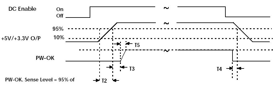
Although there is no requirement to meet specific timing parameters, the
following signal timings are recommended:
2ms < T2 < 20 ms
100 ms < T3 < 2000 ms
T4 > 1 ms
T5 < 10ms